716.694.4000
Toll Free: 800.333.5300
716.694.4000
Toll Free: 800.333.5300
To ensure operator safety and maintain productivity, a regular press inspection and maintenance program should be employed. This program should maintain records of inspections; preventative maintenance and repairs for each press. Should you have any questions, contact a Kenco Press specialist for assistance.
On a daily basis:

Oil fittings are installed on each main crankshaft bearing, on the outside hub of the flywheel, on top of the connecting rod, and on each ram guide. Each oil passage has a felt oil wick to retain the oil over an eight (8) hour period. When oiling, always allow sufficient time for all oil to saturate wick.
On a monthly basis:
On a semi-yearly basis:
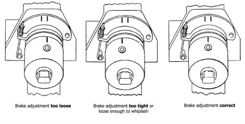
A front damping brake is installed as standard equipment on all Kompac presses.
Adjust the brake so that the mark on the connecting rod is near the center of the release area (see illustration for the ideal stopping condition). If the brake is too tight, the crankshaft will stop prematurely and be partially engaged. This is also true if there is heavy drag on the ram or the die set. If the brake is adjusted too loosely, the same action will occur, but in a different manner; the crankshaft will coast completely through the backside of the cam and whiplash into partial engagement. This condition must be corrected as it will prematurely damage the clutch parts. The brake is best adjusted after the installation of any dies and tooling due to the added mass.

The roller clutch on the Kompac presses are packed in roller bearing lubricant at the factory. Unless grease seals are broken NO lubrication is required for two years (4,000 hours.).
CAUTION: Prevent any oil or grease from entering the roller clutch area. Contamination will cause malfunction within the roller clutch and serious damage may be incurred. The oiled felt wick will provide sufficient lubrication for the clutch drive rollers.

The solenoid assembly was updated for Kenco 3K and 5K Kompac presses in June 2016 and is included in Kenco presses built after this date. The updated design includes an improved roller clutch plunger and plunger release spring with modified hardware. When replacing the solenoid on Kenco Kompac presses manufactured prior to June 2016, you must upgrade to the current kits (K027 for 3K or K039 for 5K). After the solenoid assembly has been updated, the individual components can be purchased as needed. Note: The new plunger release spring #135404 is NOT compatible with the previous assembly that used the now obsolete #121550 spring.
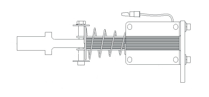
Proper seating of the solenoid when energized is necessary to prolong the life of the solenoid. Misalignment, missing brackets/spacers or incorrect installation will cause the solenoid to overheat and can result in premature failure.

![]()
Taber Materials Test & Measurement | Taber Transducer
Copyright © 2016-2026 Kenco Press.
Buffalo Web Design by 360PSG | Powered by 360CMS